Game Designer: Unknown
Game Designer: Unknown
Time Warden
King of the Hill ESP32 Timer
V6


Update 2026-10-24:
Say Hello to "Time Warden" my latest microcontrolled timer design that replaces the FrankenTimer. This newest version focuses on simplifying the build process, reducing overall cost, and improving communication between multiple units. Multi-unit communication still to come.
To achieve these improvements, the new design uses updated hardware components and will not be backwards compatible with the FrankenTimer. While the FrankenTimer remains a solid design, it performs best as a standalone unit. The new system is being built with multi-timer setups in mind.
All existing FrankenTimer resources will remain available; however, I do not plan to release any further code or hardware updates for that platform. Links to the old design can be found Here.
Introduction
I built my first timer back in 2021 and it has evolved through several iterations culminating in this latest version, the "Time Warden". Over the years of game play, I've been able to refine the timer down to the most essential components. While I was very proud of the FrankenTimer, I wanted to make it even easier for clubs to get timers so I completely redesigned my timer from the ground up.
I designed, built and programmed this from scratch. Unlike my previous version, I have decided to try and monetize this version. I have not decided exactly what that looks like. For the moment I am not posting the code and STL files while I figure that out but since I am starting to send these out into the world I did want to update this page.
Below are the essential building blocks for building a microcontroller based timer for king of the hill and other game modes. More to come on how you can get the program, buy kits and assemble it yourself. It will require soldering and other basic modding skills. While it may appear overwhelming, I break it down into manageable steps. I will also be building units to sell.
I designed it with hobbyists in mind, by using parts modders are already familiar with, along with 3D-printed components. I’ve stripped it down to what really matters for gameplay, which makes it easier to assemble and produce.

The write up, wiring diagram, and microcontroller code of this website is licensed under the Creative Commons - Attribution - Noncommercial - ShareAlike license.
Table of Contents
Parts List:
Amazon Affiliate Links Included
Total Cost: Really depends on if you have some items already available. The challenge is that many things come in packs.
Base Unit
Uncommon Items
$15 - ESP32 (2 pack, only need 1)
$10 - ESP32 Antenna (2 pack, only need 1)
$23 - LEDs (16 ft, only need about 3 ft)
$6 - 220 ohm resistors (100 pack, only need 5)
$7.50 - Dupont 15 cm Wires (Recommended)
$20 - USB Power Bank (2 pack, only need 1)
$15 - USB Connectors (4 pack, only need 1)
$10 - LED Easy Connect (Optional)
Common Items
$7.50 - 16A Microswitch (12 pack, only need 2)
$8 - Heat Shrink Tubing (Variety Pack)
$8 - Electrical Wire Twist Caps (Variety pack, only need 4)
$17 - M3 Bolts (Assorted pack)
Tools List:
-
Computer
-
Cable to connect ESP32 to computer
-
Soldering Iron and solder
-
Wire strippers
-
3D Printer
Step 1: Install Heat Inserts
Install the heat inserts per the figures below.

Step 2: The microswitches

For the switches, solder a wire with a female DuPont connector to the terminals that go to the pins. Solder some 20 awg black wire to the GND terminals.
Don’t forget to add the heat shrink tubing to both.
Don't forget to leave enough slack in the wires for assembly and disassemble.
Step 3: The LEDs


Soldering to the LED strip is a real pain. You can buy quick solderless connectors to avoid the hassle if you want, but you can also just solder to the LED.
The signal wire (ie Din) is a cut DuPont wire with the female end still attached. The power and negative power use 20 awg wire for the 36 LEDs used by the timer. 20 awg works really well with the quick connects if you are using them.
Solder two 220 ohm resistors to the wire with the female DuPont connector. Solder a bit of wire to the otherside of the resistors. I use 20 awg but you can use the excess from the DuPont wire. Make sure to cover this connection with heat shrink.
You will likely have to cut away some plastic coating that is covering the LED. If you use the quick connect then hook all the wires up otherwise solder a red 20 awg wire to the +5V terminal and a black 20 awg wire to the GND terminal.
The solder connection to the LED strip is not very strong so add some glue and put heat shrink tubing over the end of the strip. I also zip tie the wires together at this location for added strength.
Step 4: USB Connector

Warning! make sure the battery is disconnected when doing the wiring.
Prior to feeding the power cord wires out of the housing, tie a loose knot in them to act as a stop to prevent the wires from pulling on the connections. Feed the wires through the hole and then connect the red 20 awg wire to the "V+" terminal and the black 20 awg wire to the "-" terminal.
Step 5: ESP32 Antenna
This can be a little finicky to get attached but you basically just need to orientate it properly and then snap it into place.
Step 6: Connecting Wires To The ESP32/ Wiring Schematic:
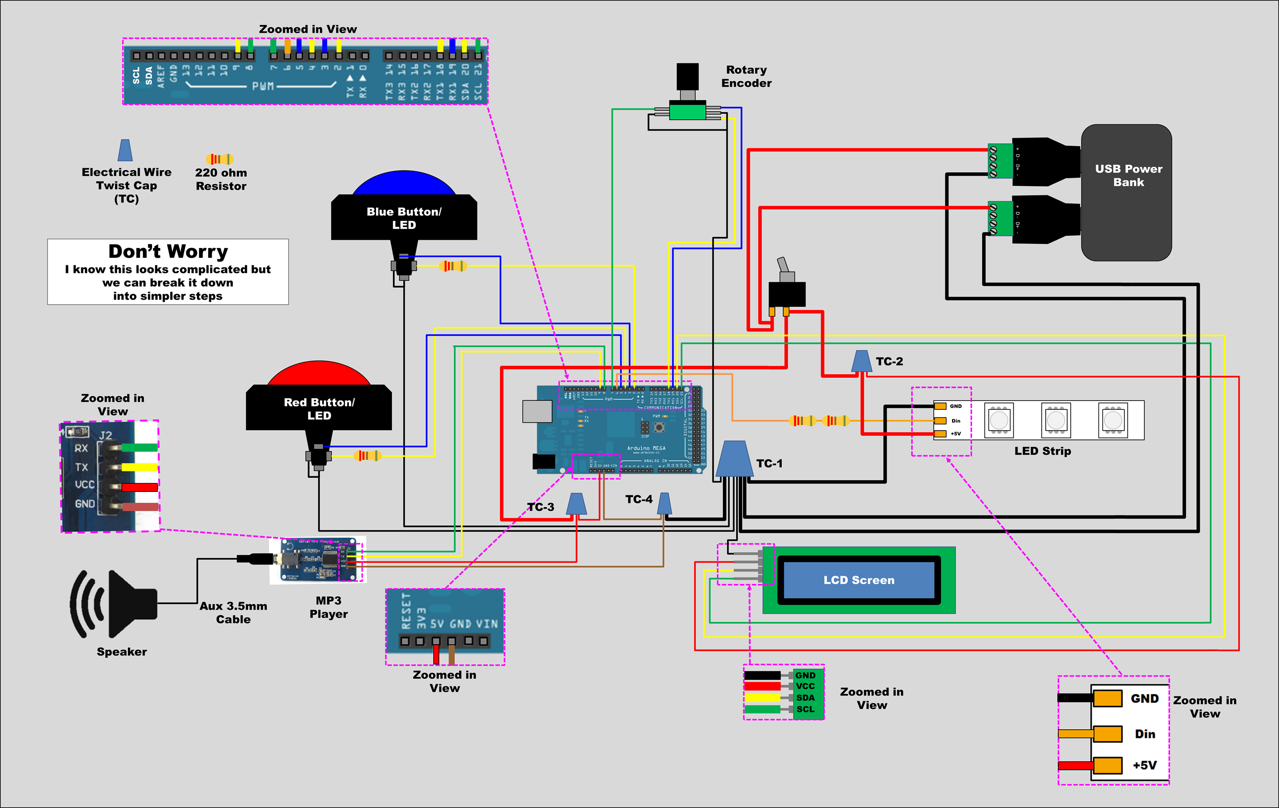
Here is my attempt at a wiring diagram. The entire diagram may be a little intimidating but the above steps break it down into simple steps.
You'll notice each step has a simple wiring diagram showing which pin or twist cap (TC) the wire connects too. The full wiring diagram is to help understand the overall big picture. The big thing here is showing that all the black wires get combined into one twist cap and the red wires into another twist cap.
Attaching the wires to the ESP32 is where the DuPont wires come in useful. You could solder to the ESP32 if you really want to but I don't find it that necessary for casual play, however if your players tend to knock the timer over then you might like to consider it.
Step 7: ESP32 Code:
Unlike my previous version I have decided to try and monetize this version, although I have not decided exactly what that looks like. For the moment I am not posting the code and STL files while I figure that out but since I am starting to send these out into the world I did want to update this page. More to come on how you can get the program, buy kits and assemble it yourself.
This new code will require you to use the Arduino IDE program which means you will also need to download libraries. Arduino IDE is free and can be downloaded Here.
Warning! The LEDs are tied to the ESP32 so make sure you are plugged into the USB bank whenever the LEDs will be on, other wise you could fry the ESP32. The ESP32 start up code will not turn on the LEDs until you advance in the menu.
More to come on how to upload the code.
Step 8: Testing/ Operating the Timer/
Admin Interface
Check out the videos on how to navigate the menu.
Setup Videos: