Game Designer: Unknown
Game Designer: Unknown
V5 FrankenTimer Housing
3D Printable Housing for KoTH Timer

Update 2026-04-26:
I’m currently developing a new timer design to replace the FrankenTimer, with a target release by the end of 2026. This next version focuses on simplifying the build process, reducing overall cost, and improving communication between multiple units.
To achieve these improvements, the new design will use updated hardware components and will not be backwards compatible with the FrankenTimer. While the FrankenTimer remains a solid design, it performs best as a standalone unit. The new system is being built with multi-timer setups in mind.
All existing FrankenTimer resources will remain available; however, I do not plan to release any further code updates for that platform. If you’re considering building a timer in the near future, you may want to wait for the upcoming version.
The models available for download and information on this page is licensed under the Creative Commons - Attribution - Noncommercial - ShareAlike license.
The files are all oriented in the correct print configuration so you should be able to just drop them into your slicer. I did not need to use any supports when printing these although you may like too for the shell as there is a portion that is completely over hung (my printer was able to bridge it just fine). I was able to print all parts using a Ender 3.
The guide below is meant to be paired with the video at the top of this page and the electronics guide.
Let's make building FrankenTimer easier.
One of my biggest lessons learned in this journey is that wire management is essential and that making custom wires/ housing is time consuming. I therefore set out to address those two topics.
Having been in this hobby for awhile I should have known people would want bigger battery compartments. Version 5 removes the battery from the core to allow for a larger battery compartment and thus greater variety of USB power banks. It also provides a bit more versatility in deciding what configuration you want to build.
Version 4 still works just fine and can be found here.
It is not necessary to utilize my 3D models but it should make building the timer significantly easier. There are three sets of files: the core, the shell and the alternate.
Core
The core is the brain of the timer and is where the Arduino, LCD, charging cable, data cable, rotary encoder, power switch, and twist caps are stored. The core can be installed in the shell I designed or into a container of your choosing. You will need all of the files from the Core folder.
Shell
The shell is designed to house the core and makes for a compact timer unit that can be easily transported and stored. The shell is also where the buttons, LEDs, battery and mp3 are mounted. For this configuration, in addition to the core files you will need the files in the Shell folder. You will not need the files in the Bucket Alt folder.
Alternate (New)
The alternate models are meant to be utilized when you decide to mount the core in a container other than my shell. It provides mounting points and cover plates. For this configuration, in addition to the core files you will need the files in the Bucket Alt folder. You will not need the files in the Shell folder. This should be pretty intuitive based on the assembly guide video for the shell but I will make it's own video eventually.


Parts List for Housing:
Amazon Affiliate Links Included
Housing Items:
$17 - M3 Bolts (Assorted pack)
$6 - #2 Screws (100 pack, only need 2-4)
$16 - M3 Heat Inserts (Qty 32)
$23 - Black Filament (Qty 1.5 kg)
$6 - Zip Ties (Assorted pack, probably around 10 needed)
You can pick up some of the items from home depot but I included links for those who want them. For the core you can use whatever color filament you want. For the shell you will want to use a darker filament to provide contrast to the LEDs. You may be able to scrounge the #2 screws from an old blaster.
Tools List:
-
3D Printer (I used an Ender 3)
-
Soldering Iron and solder (I also had special tips for my heat inserts)
-
Screw driver
-
Tape (I used mailing tape)
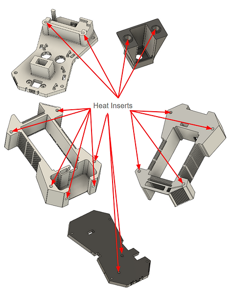
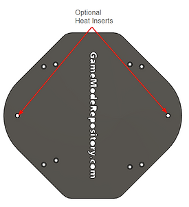
Step 1: Install Heat Inserts, cut wires & solder all the Joints
Install the heat inserts per the figures below. The optional heat inserts are dependent on the configuration you want to use. Check out the Video for a more detailed explanation.

Cut wire lengths per the table below. The connector column indicates which connector remains on the wire you will use. I also used some tape so I could label which wire was which.

For soldering check out the assembly video at the top of the page and the electronics guide.
Step 2: Install Components
Mount the Rotary Encoder, LCD, and Arduino using M3 8mm bolts at the locations indicated below. For V5 I switched from 10mm bolts to 8mm bolts but you can still use either. Video


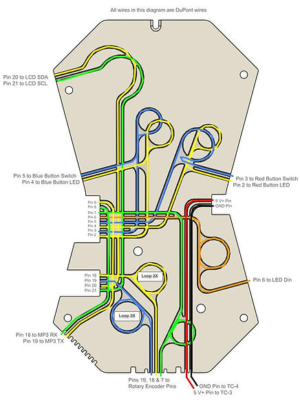
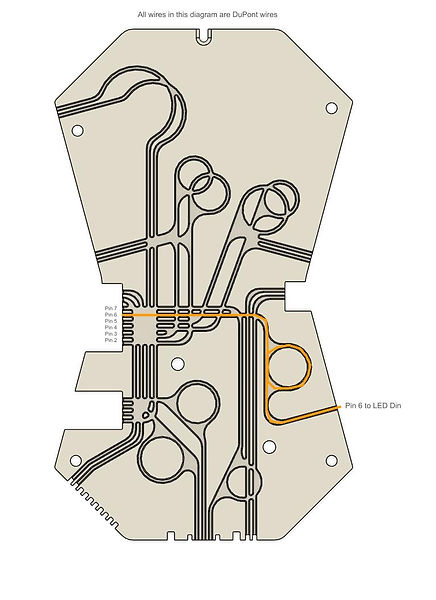
Step 3: Install wires in Layer 5 & 6
Temporarily install layer 5 onto layer 6. Install the wires into the Arduino, layer 6 and layer 5 by feeding them into the wire channels in the prints. Below is the full diagram but I also broke it out into smaller diagrams below. Video


Step 4: Install power switch and wires in Layer 3
Install power switch and wires onto layer 3. I left the groove so they can go out the end but for the actual assembly you will want to feed them through the channel of L5 and L6. Video

Step 5: Assembly Layers 3, 5, & 6
Use M3 16mm bolts to attach layers 3, 5, & 6 together. Layer 4 and 7 are no longer part of the core. Then connect the relevant wires. Video


Step 6: Install battery base, MP3 base (Optional), MP3 drawer (Optional), shell, charging cable door, LEDs, buttons, name plates, and top cover
If using the MP3 base, you have the option to mount the core directly to the MP3 base and to then mount that to the shell using M3 16mm bolts, The battery base then bolts through the MP3 base into the shell using M3 35mm bolts.
As an alternative you can skip the previous way of mounting the parts together and instead just use M3 35mm bolts to mount the core, MP3 base and shell to the battery base.
If you are not using the MP3 base then you can use M3 16mm bolts to mount the core and shell to the battery base.
Use M3 16 mm bolts to attach the charging cable door and top cover.


Step 7: Alternate Configuration


Warning! make sure the battery is disconnected when doing the wiring.
Solder two red (positive) 18 awg wires to each of the terminals on the on/off (power) switch. Install the on/off switch in the housing prior to connecting the wires to the other locations. Two wires from one terminal go to the USB connectors (which can just be screwed on), the two wires from the other terminal go to the twist cap junctions TC-2 and TC-3.
Connect the the black (negative) 18 awg wires from the USB connectors to twist cap TC-1. Connect a 18 awg wire between TC-1 and TC-4. Next connect the brown/black (GND) wire from the buttons, LCD, rotary encoder, LED to TC-1. Connect the Arduino and mp3 GND wires to TC-4. I run all of the DuPont wires to the twist cap before I cut them so they are nice and neat.
Finally, connect the LED and LCD 5V wires to TC-2 and the Arduino and mp3 5V (VCC) wires to twist cap TC-3. The reason for the extra twist caps is to make assembly easier and to possibly allow for future hardware upgrades.